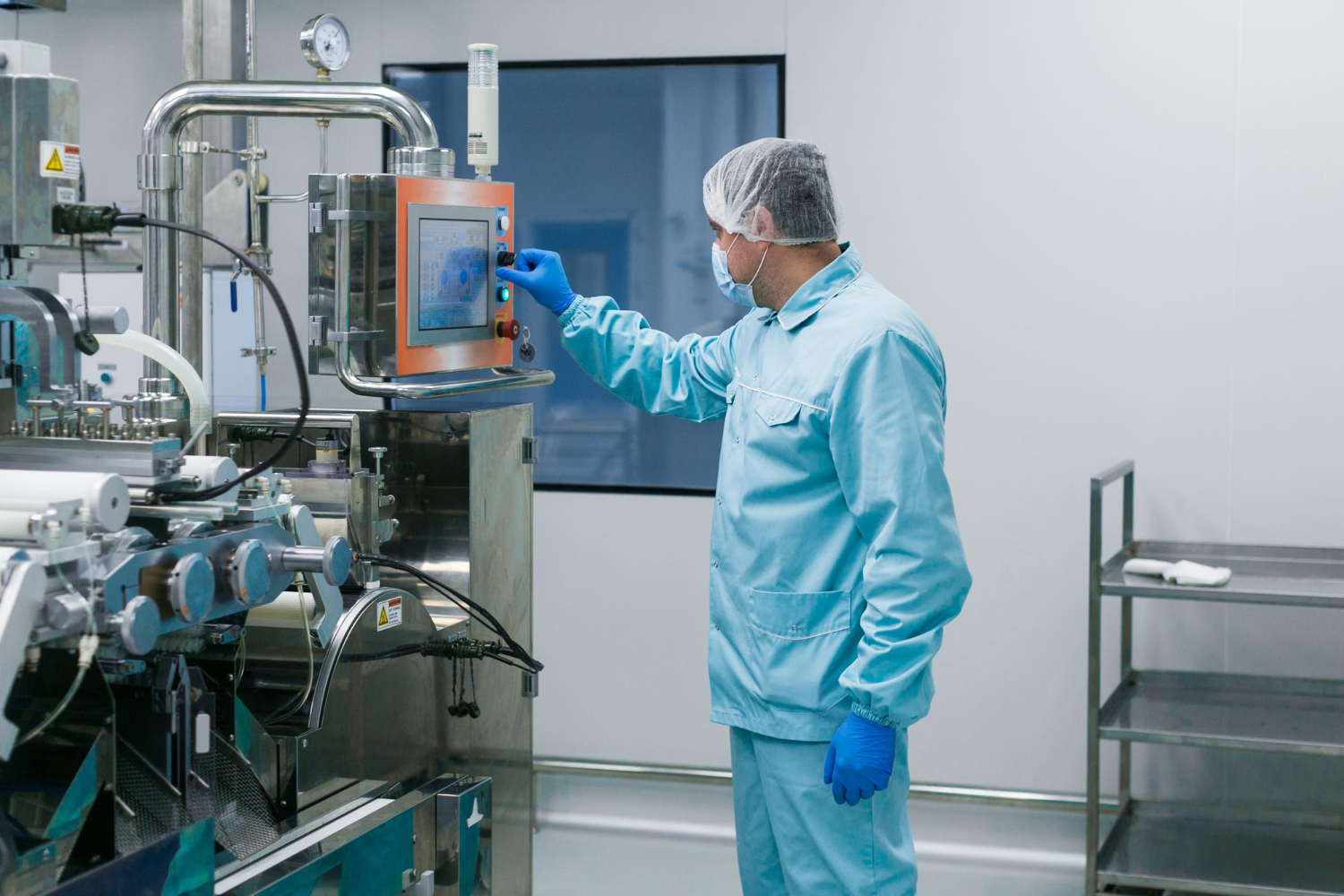
A vision cell measures a machined bracket at 12.03 mm and passes it. A week later the same part reads 12.19 mm and fails. Nothing changed on the part. Something changed in the camera’s relationship to the world — and nobody noticed, because the numbers still looked plausible.
That relationship is the camera’s extrinsics: the rotation and translation that place the camera in world coordinates. It is one of the quietest failure points in dimensional inspection, precisely because a wrong extrinsic calibration does not throw an error. It produces measurements that look right and are wrong. The core claim of this article is simple: on any position-critical or dimensional inspection task, extrinsics are not a one-time setup step — they are a maintained quantity, and treating them otherwise builds silent bias into every measurement downstream.
What Camera Extrinsics Mean in Practice
Intrinsics describe the lens; extrinsics describe where the camera sits in space. The intrinsics describe what happens inside the camera — focal length, the principal point, lens distortion — the parameters that map a 3D ray in the camera’s own frame onto a pixel. The extrinsics describe where the camera sits relative to something external: a rotation matrix and a translation vector that transform points from a world (or robot, or fixture) coordinate frame into the camera frame.
Put concretely: intrinsics tell you how the lens bends light onto the sensor; extrinsics tell you where the camera is standing and which way it is pointing. In the standard pinhole formulation used by OpenCV’s calibrateCamera and the projection routines built on it, a world point is first rotated and translated by the extrinsics into camera coordinates, then projected through the intrinsic matrix onto the image plane. Both halves have to be right for a pixel to mean a physical location.
The distinction matters because the two halves fail differently and drift on different timescales. Intrinsics are a property of the lens and sensor; barring a lens swap or a refocus, they are stable. Extrinsics are a property of mounting — and mounting is the thing that gets bumped, re-seated, and thermally warped on a production floor. A vision system can hold perfect intrinsic calibration for years while its extrinsics quietly walk off after a single fixture change.
Extrinsics vs Intrinsics: Why the Distinction Decides Your Calibration Plan
Intrinsics belong to the camera body and change only when optics are swapped; extrinsics shift whenever mounting hardware moves or thermal expansion occurs. Intrinsic calibration belongs to the camera-and-lens assembly and is re-done when that assembly changes. Extrinsic calibration belongs to the installation and needs re-validation whenever the physical relationship between camera and workpiece can plausibly have moved.
| Aspect | Intrinsics | Extrinsics |
|---|---|---|
| Describes | Lens + sensor geometry | Camera pose in world/robot frame |
| Parameters | Focal length, principal point, distortion | Rotation (R), translation (t) |
| Changes when | Lens swap, refocus, sensor replacement | Camera bumped, fixture re-seated, thermal shift, robot re-homed |
| Typical drift timescale | Rarely, discrete events | Continuously and after handling |
| Estimated with | Checkerboard / ChArUco target, multi-pose capture | Known-pose target, hand-eye calibration, fiducials |
| If wrong, you get | Distorted / mis-scaled image everywhere | Correct-looking measurement with systematic position bias |
The practical consequence is that a calibration protocol which only re-checks intrinsics is checking the half that rarely breaks while ignoring the half that breaks routinely. We see this pattern regularly on lines that were commissioned carefully and then never re-validated: the intrinsic numbers are pristine, and the extrinsics have drifted a fraction of a degree that nobody can see by eye but that shows up as tenths of a millimeter at the part.
How Are Extrinsics Estimated and Validated on a Line?
Position a calibration target—checkerboard or ChArUco board—within the world coordinate frame, then solve for the rotation and translation that map camera pixels to millimeters on the factory floor. Solving the perspective-n-point problem (OpenCV’s solvePnP and its variants) gives the rotation and translation that best explain where the target’s known points land on the sensor. The residual reprojection error from that solve is your first and cheapest quality signal.
For a camera mounted on or observing a robot, the problem becomes hand-eye calibration: recovering the transform between the camera frame and the robot’s end-effector or base frame, so that a pixel detection can be turned into a coordinate the robot can move to. This is the classic AX = XB formulation, and it is where a great deal of coordinate-guided inspection and pick-and-place accuracy is won or lost. A small rotational error in the hand-eye transform is harmless near the calibration point and grows linearly with reach — which is exactly why it evades a single spot-check.
Validation is a separate act from estimation, and conflating the two is a common mistake. Estimation fits parameters to the data you gave it; validation checks those parameters against data you held back. In practice that means measuring a known artifact — a gauge block, a certified reference part, a fiducial at a surveyed location — and confirming the system reports its true dimension within tolerance. A calibration that solves with low reprojection error but reports a gauge block 0.15 mm off has passed estimation and failed validation. The gauge block is the one that matters.
A worked re-validation check (explicit assumptions)
Assume a fixed camera measuring a machined feature, a stated tolerance of ±0.1 mm, and a certified gauge artifact placed at a known location in the work area. The check is:
- Baseline at commissioning. Measure the artifact across the field of view (center and corners). Record reported vs. certified dimension. On a well-conditioned setup this lands inside tolerance — sub-0.1 mm is achievable on a calibrated cell (observed pattern across our manufacturing vision engagements; not a published benchmark — the achievable number depends on optics, working distance, and part geometry).
- Define the trip line. Set an alarm threshold at a fraction of tolerance — e.g. flag when the artifact reads more than ±0.05 mm off, well before it would fail a real part.
- Re-measure on cadence. Re-run the artifact check daily or per-shift for coordinate-critical cells, and always after any event that could have moved the camera or fixture.
- Trend, don’t spot-check. A single reading tells you almost nothing; a slow walk in the artifact reading over days is the drift signature you are hunting.
The point of the artifact loop is that it turns extrinsic drift from an invisible bias into an observable, trendable number — the same logic that makes object detection metrics like precision, recall, and mAP useful for classification quality also applies here: you cannot manage what you do not measure against ground truth.
When Do Extrinsics Actually Matter?
Many defect-detection pipelines tolerate several degrees of rotational error without missing flaws, so universal sub-millimeter extrinsic accuracy becomes expensive theatre. The dividing line is whether the task consumes position or only appearance.
A cosmetic pass/fail classifier — is there a scratch, is the label present, is the surface the right color — barely cares about extrinsics. The pixels carry the signal, and a fraction of a degree of camera rotation does not change whether a scratch is a scratch. Many appearance tasks run on the same 2D CNN backbones used across production inspection, and those models are learning texture and shape, not metric coordinates.
The moment the task produces a number in millimeters, or a coordinate a robot will move to, extrinsics become load-bearing. Measuring a gap, checking a hole position, verifying a part fits a spec envelope, guiding a gripper — all of these turn pixels into physical positions, and that turn is the extrinsic transform. Here an unvalidated calibration does not degrade gracefully. It hands you a wrong answer with full confidence.
Quick answer — is this task extrinsics-sensitive?
- Does the output include a dimension in real-world units? → Extrinsics-sensitive.
- Does a downstream actuator move to a position derived from the image? → Extrinsics-sensitive (and hand-eye calibration applies).
- Is the output a class label, presence check, or appearance grade? → Largely extrinsics-insensitive.
- Does the task combine both (e.g. detect and locate)? → Treat the locating half as extrinsics-sensitive.
How Does Extrinsic Drift Show Up — and How Do You Catch It?
Mechanical creep, thermal cycling, and vibration degrade extrinsic parameters silently over weeks. The failure signature is a measurement population that slowly shifts its mean while its spread stays the same — the parts are as consistent as ever, they are just consistently reading a little high or a little low. If your QC gate is set on the raw measurement without an artifact reference, that shift shows up as a rising false-reject rate on good parts, or worse, a rising false-accept rate on marginal ones. Either way the first symptom is usually attributed to the parts, the supplier, or the machining process — not the camera.
The mechanical causes are mundane and worth naming, because they are the events your re-validation cadence should key off. A camera bumped during cleaning or maintenance. A fixture re-seated after a changeover. Thermal expansion shifting a mount over a shift as the cell heats up — a genuinely underrated cause, because it is periodic and reversible, so a camera that reads correctly in the morning can drift by afternoon and recover overnight. A robot re-homed after a fault, invalidating a hand-eye transform that was correct an hour earlier.
Detection comes down to keeping a ground-truth artifact in the loop and trending its reading, as in the worked check above. The diagnostic payoff is real: a documented calibration and re-validation cadence collapses fault diagnosis from “is it the parts, the process, or the vision system?” into a single question you can answer in minutes by re-measuring the artifact. Without that reference, teams burn days chasing a machining problem that does not exist. This is the same discipline that separates a robust production pipeline from a demo — and it is a recurring theme in what a computer vision consultant actually scopes before a system ships.
Does the Machine-Vision vs Computer-Vision Choice Change How Extrinsics Are Handled?
Reframing extrinsics as pose rather than calibration highlights which variables matter during troubleshooting. Traditional machine-vision toolchains are built around metrology from the start: explicit calibration workflows, gauge-repeatability studies, and an audit trail that a quality engineer can defend. Extrinsic calibration is a first-class, documented artifact in that world because auditability and metric accuracy are the whole point. A learned computer-vision pipeline, by contrast, often enters through the appearance door — a model trained to classify or detect — and the metric layer is bolted on later, sometimes without anyone owning the calibration explicitly.
Neither approach is wrong; they weigh different things. When the deciding factors are dimensional accuracy, traceability, and defensible tolerances, the metrology-first posture of machine vision is doing real work, and extrinsics get the formal treatment they deserve. When the deciding factors are handling variability, novel defect types, or appearance judgments that resist hand-tuned rules, the learned approach earns its place — but then someone still has to own the metric layer if any output is position-critical. That trade-off is exactly the scoping question machine vision consultants work through from recognition scope to production, and it is where our own computer vision practice spends a lot of its early-engagement effort: deciding which half of the problem is metric and treating that half with metrology rigor regardless of which model runs it.
What Tolerance and Re-Calibration Expectations Should You Set?
Derive your positional accuracy budget from the smallest feature you must measure, then work backward to camera placement constraints. The system’s measurement error budget has to be comfortably tighter than the feature tolerance you are gating on — a common rule of thumb is that measurement uncertainty should be a small fraction of the tolerance band so that borderline parts are decided by the part, not by calibration noise. If a feature tolerance is ±0.1 mm and your artifact check shows the system already eating half of that in bias and repeatability, you have no headroom and drift will start producing wrong verdicts almost immediately.
For re-calibration cadence, key it to events and to trend, not to the calendar alone. Coordinate-accurate and robot-guided cells warrant an artifact check per shift or per changeover plus an unconditional re-validation after any maintenance that touches the camera, mount, fixture, or robot homing. Appearance-only cells can run a far lighter regime. The documented cadence is not bureaucracy — it is the thing that keeps dimensional error inside stated tolerance rather than letting silent bias accumulate, and it is one of the production-requirement checks worth confirming before a system goes live rather than after the first batch of good parts gets scrapped.
FAQ
How should you think about camera extrinsics in practice?
Extrinsics are the rotation and translation that place a camera in a world (or robot) coordinate frame — they transform a 3D world point into the camera’s own frame before the intrinsics project it onto a pixel. In practice they answer “where is the camera standing and which way is it pointing,” and both halves of the camera model must be correct for a pixel to correspond to a real physical location.
What is the difference between camera extrinsics and intrinsics, and why does the distinction matter for inspection?
Intrinsics describe the lens and sensor (focal length, principal point, distortion); extrinsics describe the camera’s pose relative to the outside world. The distinction matters because they fail on different timescales: intrinsics are stable barring a lens change, while extrinsics drift routinely as mounts get bumped, fixtures re-seated, or mounts thermally warp — so a calibration plan that only re-checks intrinsics is guarding the half that rarely breaks.
How are extrinsics estimated and validated on a manufacturing line?
Fixed cameras recover extrinsics by imaging a known-geometry target (checkerboard or ChArUco) and solving perspective-n-point; robot-mounted cameras use hand-eye calibration to recover the camera-to-robot transform. Validation is separate from estimation: you measure a certified artifact such as a gauge block against its true dimension, because a solve can report low reprojection error yet still be metrically wrong.
When do extrinsics actually matter — which inspection tasks are sensitive to extrinsic error and which are not?
Tasks that produce a dimension in real-world units or a coordinate an actuator moves to are extrinsics-sensitive; appearance tasks like scratch detection, presence checks, or color grading are largely insensitive. The dividing line is whether the task consumes position or only appearance — an unvalidated extrinsic calibration degrades position-critical tasks silently while leaving cosmetic classifiers unaffected.
How does extrinsic drift show up in production, and how do you detect it before it corrupts measurements?
Drift shows up as a measurement population whose mean slowly shifts while its spread stays constant — parts read consistently high or low, usually first blamed on the supplier or the machining process rather than the camera. You detect it by keeping a ground-truth artifact in the loop and trending its reading, so drift becomes an observable, alarmable number rather than an invisible bias.
Does the machine-vision vs computer-vision choice change how extrinsics are handled?
Yes, in emphasis. Traditional machine-vision toolchains treat extrinsic calibration as a first-class, documented, auditable artifact because metric accuracy is the point, whereas learned computer-vision pipelines often enter through appearance and bolt the metric layer on later. Either can be correct, but if any output is position-critical, someone must own the calibration explicitly regardless of which approach runs the model.
What tolerance and re-calibration expectations should we set for a coordinate-accurate or robot-guided vision system?
Set tolerance from the part: measurement uncertainty should be a small fraction of the feature tolerance band so borderline parts are decided by the part, not calibration noise. Key re-calibration to events and trend rather than the calendar alone — an artifact check per shift or changeover plus unconditional re-validation after any maintenance touching the camera, mount, fixture, or robot homing.
Why Manual Verification Still Matters
Validation fixtures that test only planar surfaces will miss out-of-plane rotation errors until curved parts enter production. So the question worth carrying into any dimensional or robot-guided inspection scoping is not “did we calibrate the camera?” but “what artifact are we re-measuring, how often, and what number trips the alarm?” A system that cannot answer that is not measuring parts — it is trusting a number it set once and never checked again. If you are confirming whether a chosen inspection approach holds metric accuracy under real fixture and thermal conditions, extrinsic-validation validity is exactly the kind of production-requirement check that belongs in the assessment before the line goes live.